Comparison Calibration made easy with a 9190A Ultra-Cool Field Metrology Well
- 11 Dec 2020
How can a dry-well also function as a precision thermometer readout?
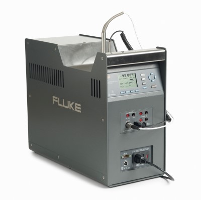
The answer is when it’s a Fluke Calibration 9190A Ultra-Cool Field Metrology Well with the process option installed.
The 9190A Ultra-Cool Field Metrology Well provides excellent stability, uniformity and plenty of well depth for calibrating platinum resistance thermometers (PRTs), thermocouples, and other industrial thermometers. The 9190A offers ± 0.2 °C display accuracy over the full range. Applying the industry standard TUR of 4:1 allows you to achieve calibration accuracy of ± 0.8 °C using the dry-well display alone.
With the process version of the 9190A model, you can automate calibrations of PRTs, thermocouples, and other industrial thermometers. The process version enables comparison calibrations against a reference PRT using the built-in readout input with an accuracy of ± 0.01 °C. When combined with other uncertainties such as uniformity, loading effect, and stability, the 9190A total measurement uncertainty with a reference PRT is as good as ± 0.06 °C. Applying the industry standard TUR of 4:1 allows you to achieve calibration accuracy as good as ± 0.24 °C.
Using a built-in reference thermometer improves the 9190A accuracy of the calibration more than three times compared to using the display alone (± 0.24 °C compared to ± 0.8 °C). It also reduces the amount of extra equipment needed to be carried when performing on-site calibrations. And with the smart connector technology, which stores your reference thermometer’s calibration coefficients, it’s easy to connect your reference thermometer to the dry-well and start making measurements immediately. When calibrating shorter sensors that don’t reach the bottom of the drywell, measurement accuracy can be improved by aligning the reference thermometer to the same immersion depth as the sensor under test. The 9190A includes a Reference Sensor Control feature which allows precise control of the block temperature at the depth to which the reference thermometer is immersed.
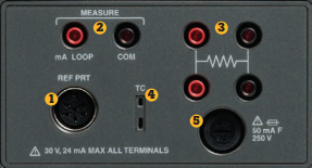
The –P (process version) panel of the 9190A. Only available with –P configurations (e.g. 9190A-A-P).
- PRT Reference Thermometer 6-pin DIN smart connector
- 4–20 mA connector allows current and/or voltage probes to be connected for measurement and includes a 24 V loop power supply when needed to power common transmitters
- PRT/RTD connector for 4-,3-, and 2- wire measurement
- Thermocouple connector (subminiature)
- Fuse for the 4–20 mA circuit
Optional process features
The built-in reference input accepts a 4-wire PRT with DIN connector termination as the reference thermometer. With this reference input, you can perform comparison calibrations against a reference PRT using the built-in readout. Temperature sensors such as 4-, 3-, or 2-wire RTDs, thermocouples, or 4-20 mA transmitters can also be connected and measured by the built-in thermometer readout.
Calibration coefficients of the reference PRT can be stored on a memory IC located inside the PRT’s 6-pin DIN termination housing (aka “smart connector” or “INFO-CON”). When you connect a reference PRT to the 9190A, the drywell automatically reads the coefficients. This makes it easy to interchange reference thermometers without reprogramming the readout. A standard 5-pin DIN connector can also be used, but the PRT’s calibration coefficients would require manual entry.
Just about any quality 25- or 100-ohm PRT can be used as a reference thermometer with the 9190A’s built-in thermometer readout as long as it is terminated with an INFO-CON. Fluke Calibration designates the INFO-CON termination as a type “A” termination. So a 5626-12 probe would be ordered as a 5626-12-A. If the reference thermometer is recalibrated, the new coefficients from the calibration report will need to be reprogrammed into the INFO-CON. This can be done from the front panel of the 9190A.
How to use the reference thermometer
Once the reference thermometer is plugged into the instrument panel of a process version (“–P”) 9190A Ultra-Cool Field Metrology Well, the display temperature of the instrument will match the temperature sensed by the reference thermometer.
Place the reference thermometer at the bottom of the calibrated zone of the dry-well. Insert the probe(s) to be calibrated into the dry-well with the reference thermometer. Be sure there is a snug fit between all inserts and sensors. Air gaps will lead to errors.
The 9190A Reference Sensor Control feature is recommended if the sensors being calibrated are too short to reach the bottom of the insert. The Reference Sensor Control feature passes temperature control of the dry-well from the internal control sensor to the external reference thermometer. Measurement errors due to axial temperature gradients can then be minimized by positioning the external reference thermometer at the same immersion depth as the probes being calibrated. Refer to the 9190A Ultra-Cool Field Metrology Well Operators Manual page 2-12 for information on enabling the Reference Sensor Control feature.
The accuracy of the measurement depends upon several factors:
- Axial uniformity (± 0.05 °C)
- Radial uniformity (± 0.01 °C)
- Loading effect (± 0.006 °C)
- Stability (± 0.015 °C)
- Reference thermometer calibrated accuracy (5616-12-A: ± 0.011 °C)
- Thermometer readout accuracy (± 0.010 °C at –95 °C)
The total accuracy in this example: ± 0.06 °C using a reference thermometer compared to the 9190A only using the display accuracy of ± 0.2 °C.
Caution: If the sensors to be calibrated have a very shallow insertion length, it may be necessary to calibrate them in a liquid bath in order for the reference probe and units under test to have sufficient immersion for an accurate calibration. Error due to stem effect should also be considered for very short sensors. For more information about calculating dry-well uncertainties, see the Fluke Calibration application note “Understanding the uncertainties associated with the use of Metrology Wells.”
How to program the smart connector
Step 1. Plug the reference thermometer into the instrument panel of the 9190A.
Step 2. From the main menu, press F4 (Input Setup) and the F3 (Ref Input). The REF INPUT (Reference Input) menu contains the parameters for the reference input to the readout module of the instrument. The Reference Input is only compatible with PRTs with ITS-90, Callendar Van-Dusen, or IEC-751 coefficients. Alternatively, the Reference Input can read straight resistance.
Step 3. Press F1 (Program Probe). The PROG PROBE (Reference Probe Setup) menu is used to set up the reference probe parameters.
Step 4. Enter the serial number of the probe. The SERIAL (Serial Number) parameter allows the user to enter ten digit alpha numeric serial number for the reference probe. Character range = {0-9, A-Z, ‘-‘, }. A minimum of one character is required. Characters entered after a blank space will be dropped. For example, if you enter TEST1678, the numeric characters will be dropped leaving the serial number as “TEST1.”
Step 5. Enter the calibration date. The CAL DATE parameter is used to enter the calibration date for the reference probe. Use the arrow keys to enter the calibration date in the format selected in DATE FORMAT.
Step 6. Enter the probe type (ITS-90, CVD, IEC-751, Resistance). The PROBE TYPE parameter is used to select the reference thermometer’s calibration characterization type. Use the left and right arrow keys to select the appropriate characterization and press “Enter” to accept the selection.
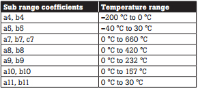
Step 7. Enter the probe coefficients. The TYPE parameter can be ITS-90, Callendar-Van Dusen (CVD), IEC-751, or resistance. The ITS-90 option is for PRTs calibrated and characterized using the International Temperature Scale of 1990 (ITS-90) equations. Subranges 4 and 7 through 11 are supported. Subrange 5 coefficients can be used in subrange 4 with negligible additional uncertainty.
Table 1. Subranges of the ITS-90.
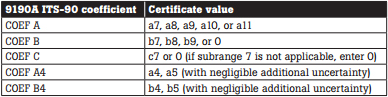
The parameters that appear when ITS-90 is selected are “Serial” (Serial Number), “Cal Date”, “RTPW”, “COEF A”, “COEF B”, “COEF C”, “COEF A4”, and “COEF B4”. These should be set with the corresponding values that appear on the calibration certificate of the PRT. The parameter “RTPW” takes the triple point of water resistance, often labeled “R0” or “R(273.16K)” on the certificate. Parameters “COEF A”, “COEF B”, “COEF C” take the an, bn and cn coefficients where n is a number from 7 to 11. Parameters “COEF A4” and “COEF B4” take the a4 and b4 coefficients on the certificate. Any ITS-90 parameter of the instrument that does not have a corresponding coefficient on the PRT’s certificate must be set to 0. Table 2 shows which parameter to set for each of the coefficients that may appear on the certificate. The example that follows demonstrates how to set the ITS-90 parameters for certain cases.
Table 2. Parameters to set for coefficients appearing on the certificate.
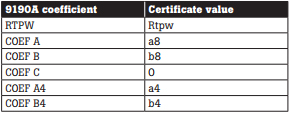
Example: A PRT was calibrated to ITS-90 and its calibration certificate states values for coefficients Rtpw, a4, b4, a8, and b8. Set the instrument’s parameters with values from the certificate as follows.
Table 3. Setting Coefficients Rtpw, a8, b8, a4, and b4.
Callendar-Van Dusen
For RTD probes that use the CVD (CallendarVan Dusen) equation, please refer to the 9190A Operators Manual or contact technical support at temperaturesupport@flukecal.com, 877-355-3225.
Step 8. Program the probe. The PROG PROBE parameter is used to tell the instrument to program an INFO-CON (e.g. Fluke Calibration type “A” probe termination) with the appropriate probe coefficients. Use the arrow keys to select “Yes” or “No”. If “Yes” is selected, the smart connector will be programmed with the appropriate coefficients 4 Fluke Calibration Comparison calibration made easy with a 9190A Ultra-Cool Field Metrology Well for the selected conversion type. For ITS-90 and CVD, the coefficient values need to be entered before programming the smart connector. For IEC751 and resistance, no values are required to program the smart connector.
Step 9. Test the coefficients. To ensure the coefficients are entered correctly, test the calculation against the table values in the calibration report. The TEST CALC (Test Reference Calculation) allows the technician to test the output of a specific conversion algorithm. Simply select the conversion type and enter a value for the requested parameter. Press ENTER; the algorithm computes the answer, and it is displayed immediately in the parentheses at the bottom of the screen, TEMPERATURE: XX.XXX.
Applications
1. If you have been bringing an external readout to improve the accuracy of your dry-well calibrations, you will have one less instrument to carry in the future. The 9190A includes a very accurate, built-in readout that can be used to achieve the accuracy you attained using an external readout.
2. If you need to calibrate sensors used for critical measurements and you have not been using a reference thermometer, then you may not have the accuracy you need to ensure your sensors remain in tolerance. Remember, calibration systems are commonly required to deliver performance that is four times the performance of the probe being calibrated. This can be challenging if you use only the display of a typical dry-well calibrator. Symptoms of this problem include:
- Frequent adjustments required after the “As Found” condition is taken.
- Interchangeability of calibration instruments appears to be an issue.
- Greater than desired downtime troubleshooting non-conforming processes.
3. If you calibrate short sensors in dry-wells, you may have an accuracy problem, since the probes do not reach the calibrated zone of the dry-well. You can solve this problem by using the 9190A Reference Sensor Control feature with a calibrated reference thermometer in the same vertical zone where the sensors are placed.
Conclusion
Using a reference probe with a Fluke Calibration 9190A Ultra-Cool Field Metrology Well is as easy as plug-and-play. It will significantly improve your accuracy in calibrating probes used in critical processes and enable you to offer better service to your customers with less equipment than before.
Content courtesy of Fluke Calibration


