Simplify Complicated EMI Measurement and Debugging
- 11 Dec 2020
As a result of faster and faster consumer electronics products, the frequency of conducting EMI tests becomes higher and higher. The continuous integration of parts in electronics products and the number of parts involved are also swiftly increasing. Besides, the demand of EMI regulations from countries and regions is getting stricter than ever. But the life cycle of electronics products is getting shorter and shorter. Hence, in order to effectively and quickly solve EMI issues at the development stage and reduce the number of times products going to the lab, a simple and easy set of tools to quickly help engineers find EMI source to greatly expedite products’ time to market is essentially required.
GW Instek's patented GKT-008 electromagnetic field probes, which are small and highly sensitive, can directly sense EMI signal energy unlike conventional near field probes which require using electric field probes and magnetic field probes to measure electric field and magnetic field separately. Users can save costs from product development cycles and the lab that is conducive to expedite time for product verification and product launch.
- The Advantages of GKT-008 EMI Near Field Probe Set
- Swiftly Simplify Complicated EMI Measurement and Debugging
- New Generation Probes to Accurately Find Radiation Source
- Problems Facing General Near Field Probes
- Practical Cases
- Video - EMC Pretest Solution
- Useful Links
1.The Advantages of GKT-008 EMI Near Field Probe Set
The conventional magnetic field probes are hollow loop probes. When the magnetic field is perpendicular to probe’s loop surface, the maximum measurement value can be obtained. The maximum magnetic field value can only be measured by rotating probe’s direction.
GKT-008 EMI near field probe features high spatial resolution and sensitivity without rotating probe’s direction to measure the maximum magnetic field value so as to identify the main radiation signal source. This probe set aims at carrying out pre-test and debug of EMI field scanner so as to effectively obtain EMI source, segmented frequency strength of EMI source, etc. that provides key indicators for resolving EMC issues. By this probe set, users can formulate solutions to amend failed products.
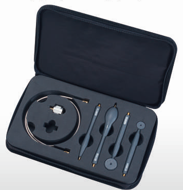
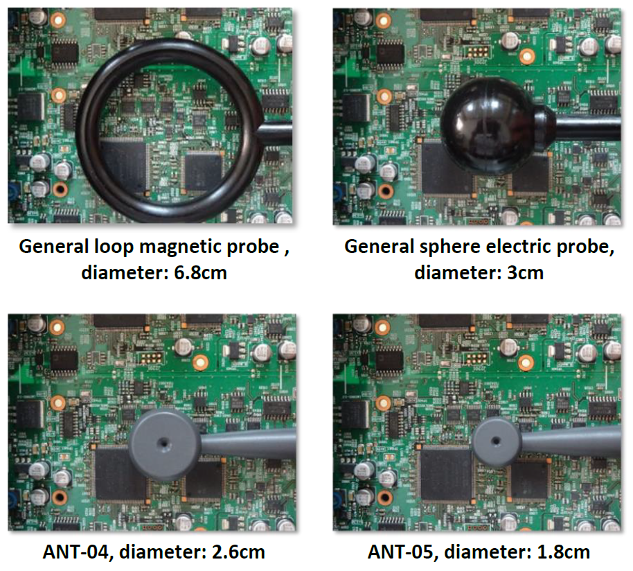
GKT-008 EMI Near Field Probe Set comprises four probes, including PR-01, PR-02, ANT-04, and ANT-05. The antenna factors of these four probes are built in the EMC Pretest function of the GW Instek GSP-9300 spectrum analyzer.
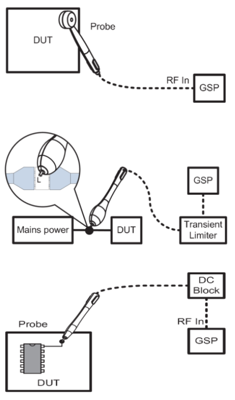
ANT-04 and ANT-05 are EMI field sensor, which can maximally sustain CAT I 50Vdc. ANT-04 and ANT-05 magnetic field probes will collocate with ADB-008 DC block to avoid damaging spectrum analyzer and the RF input terminal of DUT receiver.
PR-01 is an AC voltage probe, which can maximally sustain CAT II, 300VAC. PR-01 AC voltage probe will collocate with GPL-5010 transient limiter and BNC (M) to SMA (F) adaptor to avoid damaging spectrum analyzer and the RF input terminal of DUT receiver.
PR-02 is an EMI source contact probe, which can maximally sustain CAT I 50V DC. PR-02 electric field probe will collocate with ADB-008 DC block to avoid damaging spectrum analyzer and the RF input terminal of DUT receiver.
2. Swiftly Simplify Complicated EMI Measurement and Debugging
General issues of near field measurements:
Usually, engineers will use near field probes to conduct EMI tests for circuit verification. However, they will encounter same problems when carrying out the test.
- Probes can not quickly identify which circuit the radiation source comes from.
- Engineers have to use magnetic field probes and electric field probes separately for measurements and they have to use their experience to find the signal source.
- The angle or position of magnetic field probes will complicate the measurements.
The main reason behind these problems is that near field probes in the past are distinguished by magnetic field probe and electric field probe. In fact, engineers are concerned about how signal’s energy emits. Hence, it is very important to correctly and quickly find the major energy emission source.
Probe Size:
Normally, larger near field probes are used to sense electromagnetic field. But they can not easily identify the source of radiation. On the other hand, smaller probes will lower the sensitivity.
The difference between electric field probe and magnetic field probe:
It is very difficult to judge the real signal source by waveforms obtained from measurements of electric field probes and magnetic field probes separately. Because these waveforms are very different from each other.
The angle of probe:
The position and angle of probes also affect the measurement results and will lead to misjudgment.
3. New Generation Probes to Accurately Find Radiation Source
Light and compact:
General near field probes using larger probes to sense electromagnetic field. But they can not easily identify radiation source even though signals can be obtained due to the coverage of most circuit and parts.
ANT-04 and ANT-05 of GW Instek’s GKT-008 have the characteristics of small size and high identification resolution.
Real test comparison- setup:
Compare general EMI near field probes with GW Instek dedicated EMI near field probes ANT-04/ANT-05 via a same signal source output.
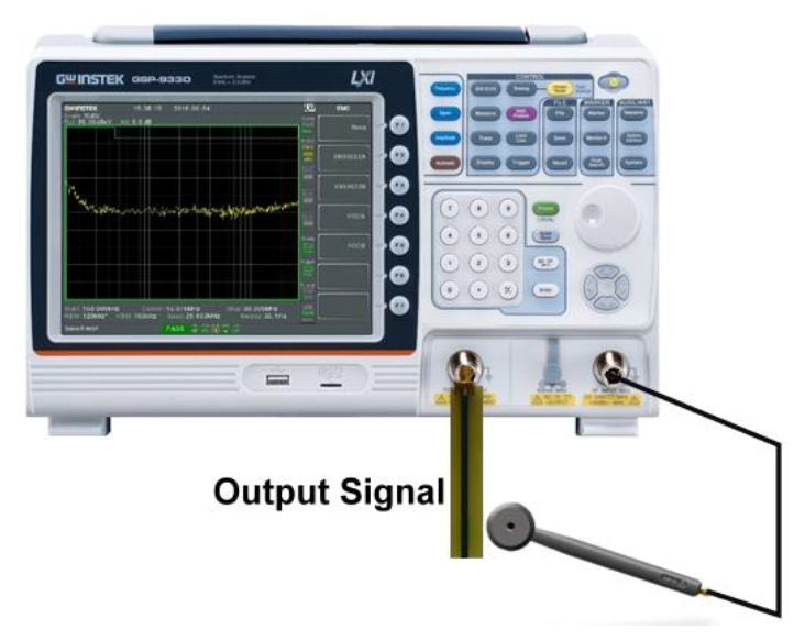
- Using TG of GSP-9330 to produce signals of 30M ~ 1GHz, 0dBm
- Connect TG with a PCB monopole antenna to simulate EMI signals produced by PCB trace
- Connect different probes with spectrum’s input terminal to compare (1)sensitivity (2)directivity
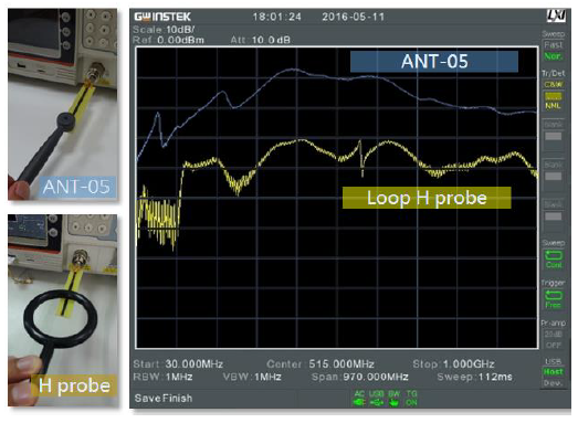
GW Instek’s probes are high sensitivity design:
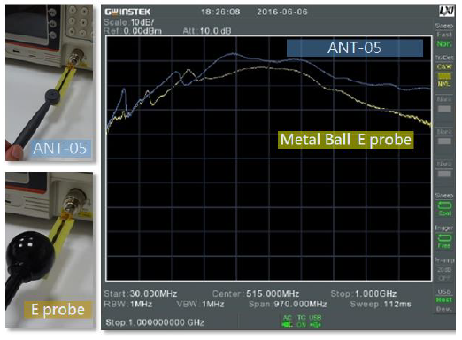
The below experiment result shows ANT-05’s size is 1/9 to that of the general magnetic field probe but its sensitivity is 20dB higher.
The next experiment result shows ANT-05’s sensitivity (especially for high frequency) is better than the general electric field probe to the scale of 5~15dB.
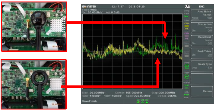
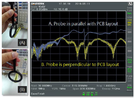
Directivity difference- the angle of probe:
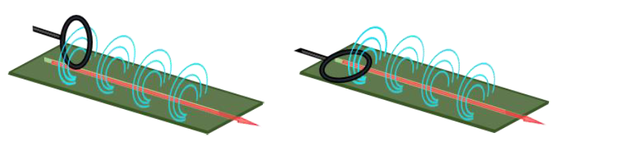
Conventional magnetic field probe’s angle makes a huge difference. The below image shows a conventional magnetic field probe in parallel with signal. After rotating the probe 90 degree to become perpendicular to the signal, the sensitivity drops 10~20dB for medium to high bandwidth. It will be very difficult to identify emission source for a product with complicated PCB trace design.
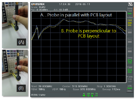
GKT-008 probes do not have angle issues. ANT-04 of GKT-008 does not have angle issues because the measured energy results from the probe in parallel or vertical to PCB trace are almost the same and stable. See image below:
Directivity difference-the maximum signal source:
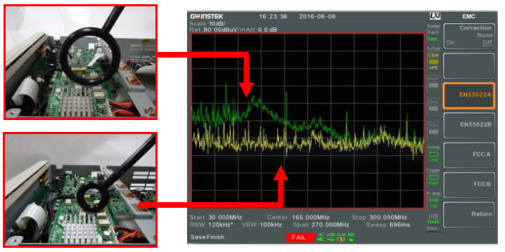
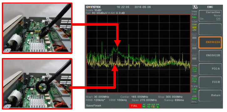
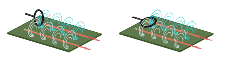
A loop probe aiming at the center of PCB trace can not guarantee the maximum signal be sensed.
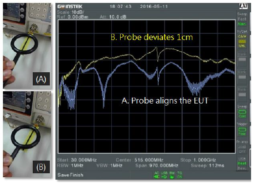
A loop probe aiming at the center of PCB trace as shown on lower left hand corner picture can not guarantee the maximum signal is sensed. The upper left hand picture shows 1cm deviating to the center obtained better sensitivity. This result is related to magnetic field probe’s operational principle. Hence, this phenomenon will result in misjudgment for electronics products with higher density.
ANT-04 obtains the maximum signal when aiming at the center of EUT.
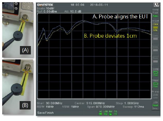
ANT-04 obtains more signals when aiming at the center of EUT as shown on the above picture. Weaker signals obtained when the probe was 1cm deviating from the center. This result serves engineers’ expectation of quickly finding the real emission source with no misjudgment.
The major advantages of ANT-04 and ANT-05:
- Small size, high sensitivity, they can accurately identify the real radiation source.
- They can directly sense electromagnetic wave's energy without conducting separate electric field and magnetic field probe tests.
- Without directivity issue.
- Simplify complicated measurement and greatly reduce EMI debugging time.
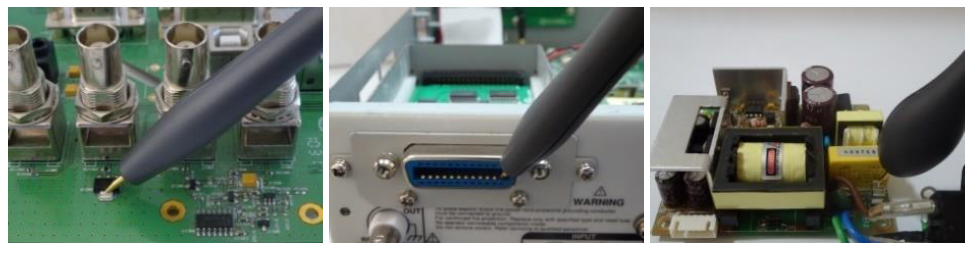
Probes can conduct contact circuit tests:
GKT-008 has contact probes to directly contact circuit for tests such as PCB trace noise, IC pin noise, power supply’s noise, etc.
4. Problems Facing General Near Field Probes
Electromagnetic wave's energy is produced by electric field and magnetic field:
Maxwell's Equations explain an important phenomenon: electric field and magnetic field coexist and mutually affect each other. These Equations describe how current and time-varying electric field produce magnetic field and how time-varying magnetic field produces electric field.
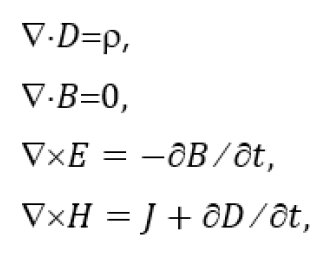
- D: Electric displacement
- P: Charge density
- E: Electric field intensity
- H: Magnetic field intensity
- J: Current density
- B: Magnetic flux density
Maxwell's Equations:
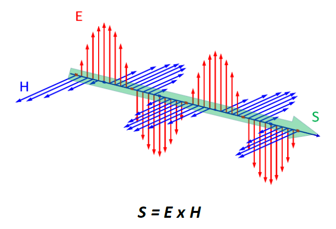
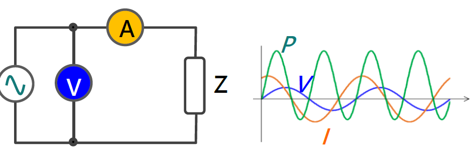
EMI signal's energy is also determined by electric field and magnetic field. If S represents energy's density, E: electric field strength, H: magnetic field strength, and Poynting theorem states S = E x H. Electromagnetic is the cross product of electric field intensity and magnetic field intensity. Therefore, it is directional.
General circuit's power is the product of voltage and current. Both current and voltage are required.
The radiation near field measurement for loop antenna mainly focuses on magnetic field:
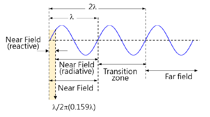
Near field and far field are defined by the distance between receiver antenna and emission source. It is called near field if the distance between receiver antenna and emission source is smaller than signal's wavelength. Near field includes reactive near field area and radioactive near field area. It is called far field if the distance is greater than wavelength, as the diagram shows. For example, wavelength for a 300MHz signal wave length λ is 1m, then, less than 15.9cm ( λ/2π) is reactive near field, less than 1m is radioactive near field and over 2m is far field. Tests closing to PCB are reactive near field measurement of near field.
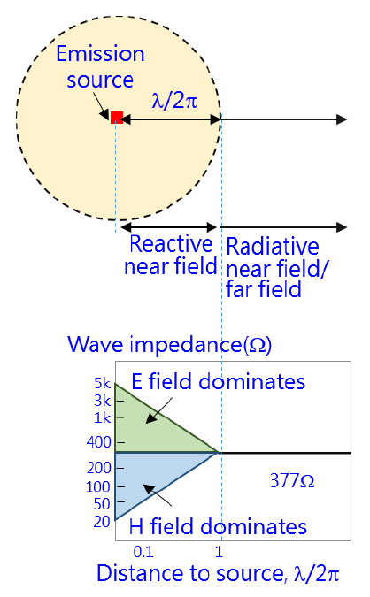
The electromagnetic wave analysis of reactive near field is related to emission source and antenna, therefore, the analysis is very complicated. The following diagram elaborates wave impedance vs. distance from emission source. Loop antenna induces large current and low voltage in near field electromagnetic wave characteristics. Its wave impedance is low; therefore, magnetic field dominates. That is why a loop magnetic field probe can sense very strong magnetic field at a low frequency bandwidth when closing to PCB. But electric field strength is not necessarily strong that can not certainly contribute to the real strong EMI signals.
Loop near field probes have directionality issue:
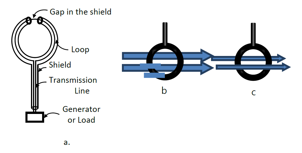
The structure of a loop magnetic field probe is shown as diagram a. If the magnetic field direction is perpendicular to loop surface (diagram b), then it can be sensed, if it is in parallel with the loop surface, then the magnetic field can not be sensed.
Problems occurred while using a loop antenna for PCB measurements:
In addition to active components, PCB trace is also the EMI emission source. Higher current passing through trace will produce higher magnetic field; trace with higher voltage such as high load impedance or open circuit trace will produce higher electric field. A probe can pick up a very strong magnetic field if two PCB traces are very close to each other despite the individual magnetic field is weak.
A. Loop probe sensing magnetic field produced by current passing through PCB layout.
B. The magnetic field of multiple PCB layouts can be simultaneously sensed
A probe aiming at the center of PCB layout can not guarantee the maximum magnetic field is sensed:
The directivity of a loop probe is likely to cause misjudgment. Diagram A below shows a probe placed directly above PCB trace can not obtain any signals. More magnetic field will pass through and stronger signals can be obtained if slightly deviating a distance.
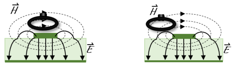
A. A probe placed directly above B. A slight distance deviation from the center
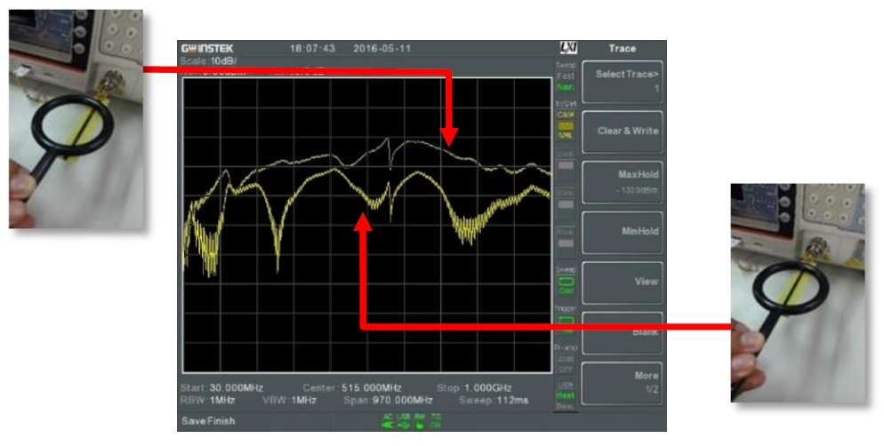
The following experiment result proved this phenomenon:
5. Practical Cases
GKT-008 has best sensitivity:
We used the same test conditions and device. At the same spot on the circuit, a conventional electric field probe, a conventional magnetic field probe and a GW Instek’s ANT-04 near field probe were used to conduct test.
The measurement of conventional electric field probe.
The measurement of conventional magnetic field probe
The measurement of GW Instek’s ANT-04 near field probe
We found that the conventional electric field and magnetic field probe have a larger difference on the measurement results and their sensitivities can not compare with that of GW Instek’s near field probe. For smaller signals, the conventional probes will produce more errors.
The correlation with the result of the lab:
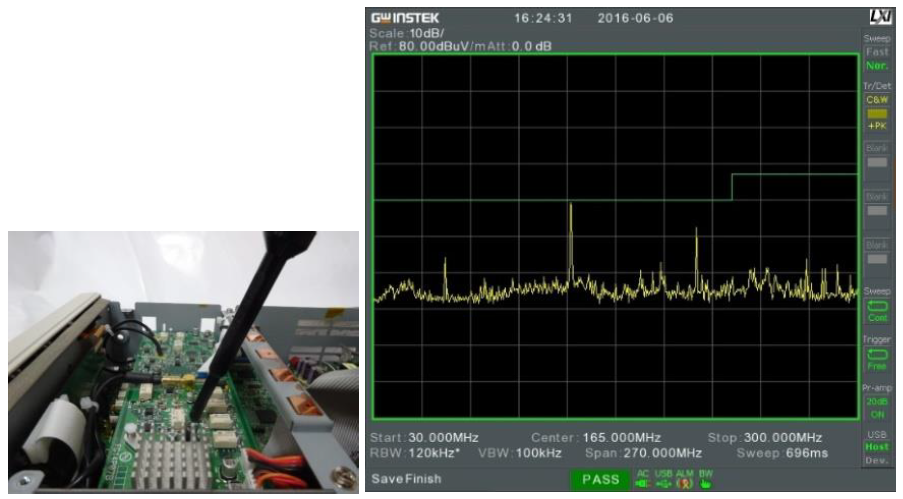
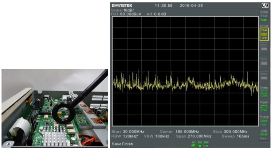
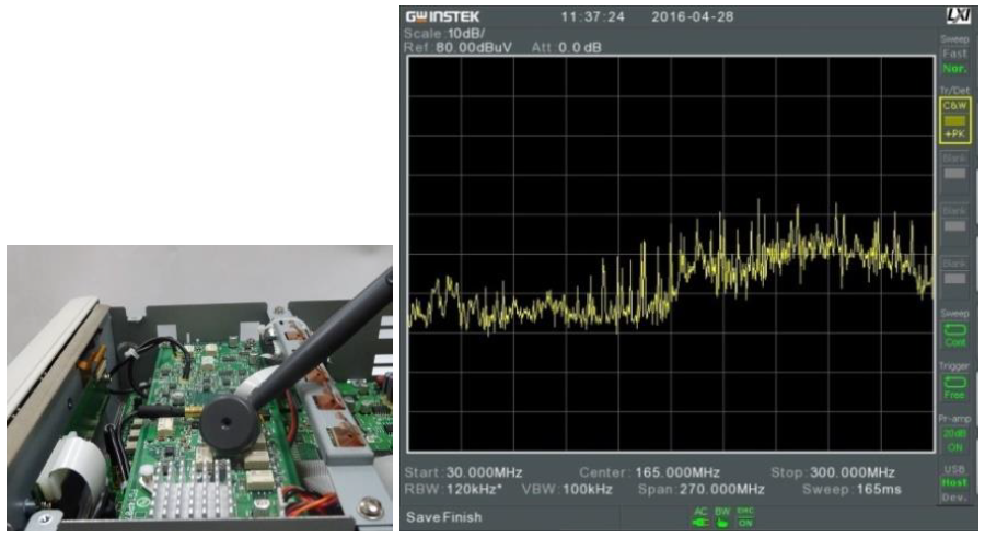
Another practical case was to directly place EUT in a 3m anechoic chamber. A switching power supply was used in a 3m anechoic chamber. The test resulted in three larger signals. Next, a conventional electric field probe, a conventional magnetic field probe and a GW Instek’s ANT-04 near field probe were used to conduct test.
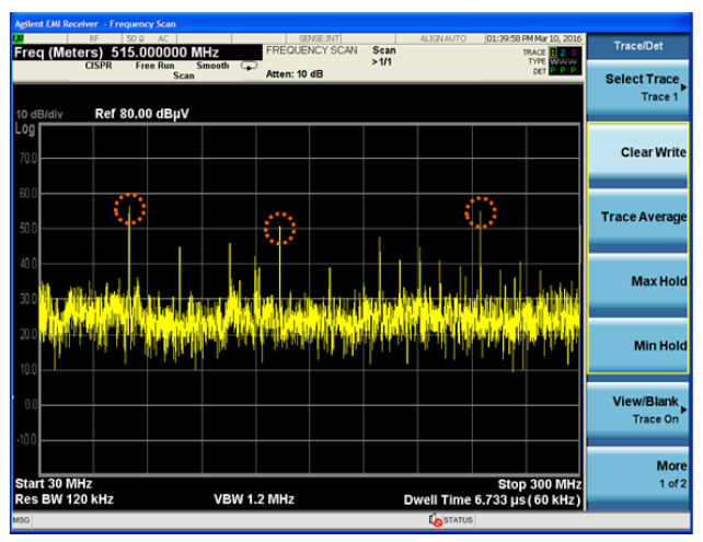
The measurement result of EUT in a 3m anechoic chamber.
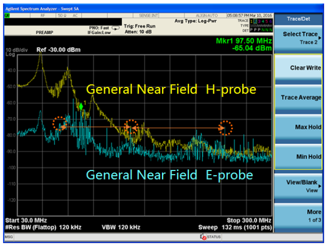
The measurement results of electric field probe and magnetic field probe testing EUT’s EMI.
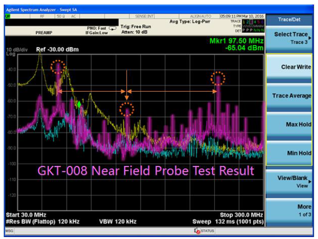
The measurement result of GW Instek GKT-008 has better reference.
We found that the measurement results of the conventional electric field and magnetic field probe yielded big difference. For magnetic field’s high frequency measurements, the conventional probes could not find signals found in anechoic chamber. For electric field, the poor sensitivity of the conventional probes could not find concealed signals. GKT-008 can find three identical signals found in the lab.
6. Video:
7. Useful Links:
- GW Instek GSP-9330, Spectrum Analyzer >
- GW Instek GKT-008, EMI Near Probe Set >
- Request a Quote >
- Request a Demo >


