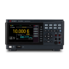
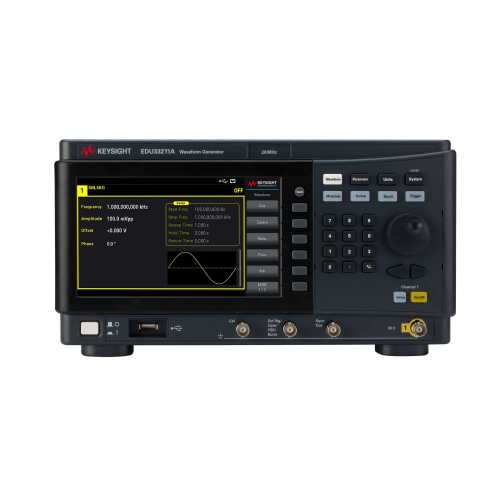
Keysight Smart Bench Essentials - EDU33211A 20 MHz, Single-Channel Function/Arbitrary Waveform Generator
Education partners save up to 30% off Keysight Smart Bench Essentials
Keysight's EDU33211A single-channel function / arbitrary waveform generator offers premium performance for an affordable entry-level instrument. Enjoy basic functions and waveforms with exceptional stability and low distortion. Benefit from flexible features for efficient task completion. Featuring USB and LAN IO interfaces for remote connectivity, 20 MHz sine and square waveforms, ramp, triangle, noise, pulse generation, and more. Experience intuitive operation with a 7-inch color display and BenchVue Basic app for control.
- Harness the power of the signature 7-inch color display for seamless parameter setup, signal viewing, and editing all at once.
- Explore a comprehensive range of options with six built-in modulation types and access to 17 popular waveforms, perfect for simulating typical applications during testing.
- Experience unparalleled precision with 16-bit arbitrary waveform capability, boasting a vast memory of up to 8 million samples per channel.
- Stay connected effortlessly with the USB and LAN IO interface, enabling remote connectivity for streamlined operation.
- Enhance your control capabilities with Keysight's PathWave BenchVue software, empowering you with convenient PC control for optimised workflow efficiency.
Simple set up and operation
Experience seamless waveform setting and parameter management with the 7-inch wide video graphics array (WVGA) colour display of the EDU33212A 20 MHz dual-channel function/arbitrary waveform generator. This innovative display allows you to view both waveform settings and other essential parameters in a single, comprehensive view.
With colour-coded keypads and intuitive display and output connectors, the EDU33212A helps prevent setup and connection errors, ensuring smooth operation every time.
Equipped with USB and LAN connectivity as standard features, the EDU33210 Series 20 MHz function/arbitrary waveform generators offer effortless remote access and control. They support various operation modes, including standard commands for programmable instruments (SCPI) language, interchangeable virtual instruments (IVI) driver, web browser, or Keysight's Pathwave BenchVue software, providing flexibility and convenience.
Moreover, the built-in USB memory port enables you to store setup parameters with a USB flash drive, maximising efficiency in your lab setup. Quickly restore the same setup across multiple function/arbitrary waveform generators or load arbitrary waveform signals with ease, saving you time and effort.
Modulation and built-in waveforms
The EDU33210 Series 20 MHz function/arbitrary waveform generators boast a versatile array of 17 built-in arbitrary waveforms, catering to a wide range of applications. Among these are standard waveforms, including sine, square, ramp, triangle, pulse, PRBS, DC, and Gaussian noise (refer to Figures 1 and 2).
In addition to these common waveforms, the generator offers a selection of specialty waveforms, each designed to meet specific testing requirements. These include cardiac, exponential fall, exponential rise, Gaussian pulse, haversine, Lorentz, D-Lorentz, negative ramp, and sinc waveforms, providing advanced functionality for diverse applications (refer to Figures 3 and 4).
Enhancing its versatility further, the EDU33210 Series features six built-in modulation types: AM, FM, phase modulation (PM), frequency-shift keying (FSK), binary phase shift keying (BPSK), and pulse width modulation (PWM). Whether you're conducting basic signal generation or advanced modulation techniques, these generators offer the flexibility and precision needed for your testing needs.
Signal Integrity: Outputting the Signals You Expect
When it comes to designing reliable systems, minimising spurious signals or harmonics is crucial for ensuring accuracy and dependability. Testing with clean, precise, and low-noise signals is essential for success.
With the EDU33210 Series function/arbitrary waveform generators, you can achieve unparalleled signal fidelity, allowing you to generate precise waveforms tailored to your most demanding measurements. This high fidelity ensures that you're accurately observing your design's characteristics, rather than artifacts introduced by the waveform generator itself.
Rest assured that with the EDU33210 Series, you can confidently trust the integrity of your measurements, enabling you to achieve optimal results in your projects.
Arbitrary Waveform with Deep Memory
Are you seeking to test your design with intricate, extended waveforms featuring various anomalies? Look no further than the EDU33210 Series function/arbitrary waveform generators. Standard with up to 8 million samples per channel deep memory, capable of handling a maximum of 1 million samples per waveform, these generators offer ample memory capacity to tackle your testing challenges head-on.
-
Instrument
Models & Options Model Number EDU33211A Maximum Frequency 20 MHz Number of Channels 1 Waveforms Standard Sine, square, ramp, pulse, triangle, Gaussian noise, pseudorandom binary sequence (PRBS), DC Built-in Arbitrary Cardiac, exponential fall, exponential rise, Gaussian pulse, haversine, Lorentz, D-Lorentz, negative ramp, sinc User-defined Arbitrary Up to 8 MSa per channel; with up to 1 MSa per waveform Operating Modes and Modulation Types Operating Modes Continuous, modulate, frequency sweep, gated burst Modulation Types Amplitude modulation (AM), frequency modulation (FM), phase modulation (PM), frequency shift keying (FSK), binary phase shift keying (BPSK), pulse width modulation (PWM) Waveform
Sine Frequency Range 1 μHz to 20 MHz, 1 μHz resolution Amplitude Flatness
(Specification) 1, 2, 12
(Relative to 1 kHz)1 Vpp < = Vout < = 10 Vpp (50 Ohm load)fOUT < = 100 KHz: ±0.1 dB100 KHz < fOUT < = 5 MHz: ±0.15 dB5 MHz < fOUT < = 20 MHz: ±0.3 dBHarmonic
Distortion (Typical) 1, 2, 12 (Relative to 1 kHz)1 Vpp < = Vout < = 10Vpp (50 Ohm load)
fOUT < = 100 KHz: -60 dBc
100 KHz < fOUT < = 1 MHz: -50 dBc
1 MHz < fOUT < = 20 MHz: -40 dBcTHD (typical) 1 fOUT = 10 Hz to 20 kHz: < 0.075% Non-harmonic
Spurious (Typical) 1, 3, 12fOUT ≤ 2 MHz: <- 70 dBc
fOUT > 2 MHz: < - 70 dBc + 20 dB / decadePhase Noise (SSB)
(Typical) 410 kHz offset: -105 dBc / Hz Square and Pulse Frequency Ranges 1 μHz to 10 MHz, 1 μHz resolution Rise and Fall Times
(Nominal)Square at 8.4 ns, fixed
Pulse at 8.4 ns to 1 us, independently variable, 100 ps resolutionOvershoot (Typical ≤ 3%Duty Cycle 5 0.01% to 99.99%, 0.01% resolutionPulse Width 16 ns minimum (adjustable with 100 ps resolution)Jitter (RMS) (Measured) 4 ≤ 5 MHz: 2 ppm of the period + 100 ps
> 5 MHz: 100 psRamp and Triangle Frequency Range 1 μHz to 200 kHz, 1 μHz resolution Ramp Symmetry 0% to 100%, 0.1% resolution, (0% is negative ramp, 100% is positive ramp, 50% is triangle) Linearity (Typical) ≤ 0.1% from 5% to 95% of the signal amplitude (Vout ≥ 1 Vpp) Gaussian Noise Variable Bandwidth 1 MHz to 20 MHz Crest Factor (Nominal) 4.6 Repetition Period > 50 years Pseudorandom Binary Sequence (PRBS) Bit Rate 1 Mbps to 50 Mbps, 1 Mbps resolution Sequence Length 2 m - 1, m = 7, 9, 11, 15, 20, 23 Rise and Fall Times 8.4 ns to 1 μS, independently variable, 100 ps resolution Arbitrary Waveforms Waveform Length 8 Sa to 8 MSa per channel (maximum up to 1 MSa per waveform) Sample Rate 1 μSa/s to 250 MSa/s, 1 μSa/s resolution Voltage Resolution 16 bits General Connector Front-panel BNC, shell connected to chassis; all inputs and output BNC connectors are chassis-referenced Function On, off, or inverted Output Impedance
(Nominal)50 Ω Isolation Connector shells for channel output(s), sync, and modulation "in" are connected Overload Protection Output turns off automatically when an overload is applied; the instrument will tolerate a short circuit to ground indefinitely Amplitude Range 6 1 mVpp to 10 Vpp into 50 Ω, 4-digit resolution
2 mVpp to 20 Vpp into open circuit, 4-digit resolutionUnits Vpp, Vrms, or dBm Accuracy (at 1 kHz Sine)
(Specification) 2,12± (2% of setting in Vpp) ± (1 mVpp) Accuracy (at 1 kHz Sine)
(Typical) 12± (1% of setting in Vpp) ± (1 mVpp) Voltage Limit Function User-definable maximum and minimum voltage limits DC Offset Range 13 ± (5 VDC minus peak AC) into 50 Ω, 4-digit resolution
± (10 VDC minus peak AC) into open circuit, 4-digit resolutionUnits VDC Accuracy (specification) 2,12 ± (1% of offset setting) ± (1% of amplitude in Vpp) ± (5 mV) Frequency Accuracy (Spec) Standard Frequency
Reference± (1 ppm of setting + 15 pHz), 1 year, 23 ºC ± 5 ºC
± (2 ppm of setting + 15 pHz), 1 year, 0 ºC to 55 ºCModulation, Burst and Sweep
Amplitude Modulation (AM) Source Internal only Carrier Waveform Sine, square, ramp, arbModulating Waveform Sine, square, ramp, noise, arb Depth 2, 8 0% to 120%, 0.01% resolution Frequency Modulation (FM) 9 Source Internal only Carrier Waveform Sine, square, ramp, arb Modulating Waveform Sine, square, ramp, noise, arb Deviation 1 μHz to 15 MHz, 1 μHz resolution Phase Modulation (PM) Source Internal only Carrier Waveform Sine, square, ramp, arb Modulating Waveform Sine, square, ramp, noise, arbModulation Frequency 2 MHz to 1 MHzDeviation 0º to 360º, 0.1º resolutionFrequency-Shift Key Modulation (FSK) 12 Source Internal or external connector Rate ≤ 1 MHz Binary Phase-Shift Key Modulation (BPSK) Source Internal or external connector Phase Shift 0º to 360º, 0.1º resolution Rate ≤ 1 MHz Pulse Width Modulation (PWM) Source 1 Mbps to 50 Mbps, 1 Mbps resolution Carrier Waveform Pulse Modulating Waveform Sine, square, ramp, noise, arb Deviation 5 0% to 100% of pulse width, 0.01% resolution Burst Characteristics 7 Type Counted or gated Counted Burst Operation Each trigger event causes the instrument to produce from 1 to 108 or an infinite number of waveform cycles Gated Burst Operation Instrument produces waveforms while the trigger is in the "on" state. For Gaussian noise, waveform generation stops immediately when the trigger is in the "off" state; all other waveforms stop after the completion of a cycle; more than one cycle might elapse before generation stops Start / Stop Phase 14 -360° to +360°, 0.1° resolution Trigger Source Internal timer or rear-panel connector Marker Indicated by the trailing edge of the sync pulse; adjustable to any cycle of the burst Sweep Characteristics 9 Type Linear, logarithmic, or list (up to 128 user-defined frequencies) Operation Characterization of linear and logarithmic sweeps occur by a sweep time during which the frequency changes smoothly from start to stop; a hold time during which the frequency stays at the stop frequency; and a return time during which the frequency changes smoothly from stop to start Direction Up (start frequency < stop frequency) or down (start frequency > stop frequency) Sweep Time Linear 1 millisecond to 3,600 seconds, 1 ms resolution Logarithmic 3,601 seconds to 250,000 seconds, 1 second resolution Hold Time 1 millisecond to 500 seconds, 1 ms resolution Return Time 0 to 3,600 seconds, 1 ms resolution Trigger Source 10, 11 0 to 3,600 seconds, 1 ms resolution Sync Out / Trigger Out
General Connector Front BNC, chassis-referenced; functions as an output Minimum Output High Voltage Minimum 1.3 V Maximum Output Low Voltage Maximum 0.1 V External Trigger Input / Gate; Input / Burst; Input / FSK Input
General Connector Front BNC, chassis-referenced; functions as input Polarity Positive or negative slope Maximum Rate 1 MHz Input Minimum Input High Voltage 2.2 V Maximum Input Low Voltage 0.6 V Minimum Pulse Width 16 ns Variable Trigger Delay 0 to 1,000 s; 4 ns resolution Latency (Typical) < 160 ns with trigger delay set to zero Jitter < 2.5 ns, rms Memory
Instrument State Store / Recall User-defined instrument states with user-defined names in the file system Power-on State Default settings or state at power-off, selectable USB File System Front-panel Port USB 2.0 high-speed mass storage class (MSC) device Capability Read or write instrument configuration settings, instrument states, arbitrary waveform Speed (Nominal) 10 MB/s General Characteristics
USB File System LXI-C (rev1.5) 10/100Base-T (sockets and VXI-11 protocols); USB 2.0 (USB-TMC488 protocol) Web User Interface Remote operation and monitoring Programming Language SCPI-1999, IEEE-488.2 Real-time Clock / Calendar
BatteryCR-2032 coin type, replaceable, > 5-year life (typical) Mechanical Size (Nominal) 314 mm W x 130 mm H x 165 mm D (12.36 in W x 5.12 in H x 6.50 in D) Weight (Nominal) 3.1 kg (6.8 lbs.) Environmental Storage Temperature -40 °C to 70 °C Warm-up Time 1 hour Operating Environment Indoor use, installation category II for AC input; pollution degree 2 Operating Temperature 0 °C to 55 °C Operating Humidity Up to 80% RH at 40 °C non-condensing Altitude Up to 3,000 meters (9842.5 ft) Regulatory Electromagnetic
CompatibilityCompliant with EMC directive (2014/30/EU)
IEC 61326-1/EN 61326-1 Group 1 Class A
Canada: ICES/NMB-001
Australia / New Zealand: AS/NZS CISPR 11
South Korea: KC mark
(South Korean Class A EMC declaration:
Information to the user:
This equipment has been conformity assessed for use in business environments. In a residential environment, this equipment may cause radio interference.)Safety IEC 61010-1 / EN 61010-1
USA: ANSI/UL Std. No. 61010-1
Canada: CAN/CSA-C22.2 No.61010-1Acoustic Noise Sound pressure level (1 m free field) (nominal) 31 dB(A) at ambient ≤ 28 °C Line Power Line Voltage 100 to 240 V, 50 / 60 Hz; 100 to 120 V, 50 / 60 Hz Power Consumption < 45 W