Cost-Effective Solution for Troubleshooting Complex Printed Circuit Boards
- 11 Dec 2020
The Challenge
Electronic products used in aerospace applications and for scientific research have two key requirements: they must have both the high performance and the reliability to withstand intense environments. To attain that performance, electronics designers often use small parts and routinely push them to their limits. But that means the parts get hot. If they get too hot, they can’t be counted on to work reliably, or for very long without breaking.
That’s the challenge Highland Technology found itself facing on a daily basis. Founded in 1984, Highland designs and manufactures standard and custom electronics for demanding aerospace, defence, scientific, and industrial applications. Its products have very high performance and reliability requirements, with PCBs that are often populated by upwards of 1,200 very small parts.
Highland’s design process starts with a specification and then the design. Its engineers iterate between the two until they learn what specifications the design can and can’t meet and how they can improve the design. Once the schematic is worked out, a PCB is designed and laid out. Manufacturing then builds a prototype, and testing in the laboratory begins.
Highland routinely pushes the parts it uses both electrically and thermally to deliver the cutting-edge performance customers demand, particularly picosecond range speeds. Hence, many of the bugs it finds are caused by components that overheat. For Highland’s engineering and test teams, the challenge is finding out exactly which components in a given design are heating up.
As John Larkin, president and chief engineer at Highland Technology, explains, “We don’t want to make unreliable products. We want products that have high performance. Thermal stress is a key part of that because small parts switching high currents and high speeds get hot. We don’t have the analytical tools to predict what component temperatures are going to be within 10, or even 20, degrees Celsius sometimes. So, we have to physically measure the temperatures in engineering and testing.”
Of course, Highland can’t just put a thermocouple on a component to measure its temperature; the parts are simply too small. Spot pyrometers also don’t work. Like the thermocouple, these instruments measure heat only at a single specific point on an object and, therefore, offer an incomplete picture of a target’s thermal properties. Plus, troubleshooting an entire PCB with a spot pyrometer would be a slow and arduous process. Visual inspection doesn’t work either since many issues — like a short in a component — are invisible to the naked eye.
The Solution - Thermal Imaging to the Rescue
For companies like Highland that routinely design and manufacture high-performance, high-reliability electronic products, understanding the thermal properties of the components used in those products is critical. It’s in these scenarios that the thermal imaging camera thrives.
Thermal imaging cameras work by detecting infrared radiation and translating it into a temperature reading. A single camera can produce thousands of non-contact temperature readings at the same time, one for each pixel in every frame of data. These readings are then converted into a map of the heat distribution of the device. This combination of visual information and accurate temperature measurement enables users to find faults (hot spots and potential points of failure) quickly and accurately — many that might otherwise be missed.
Thermal cameras also have the advantage of being easy to use and customizable to a user’s needs. And, because they are able to scan large areas at one time, they are well-suited to inspecting heat dissipation on PCBs and performing quality checks. By detecting design flaws that materialize as heat, they even help significantly shorten product development time. Moreover, with technological advances and demand on the rise, the cost of thermal cameras has come down in recent years.
“Thermal imaging is important in our testing because it often leads us to problems quickly. Suppose you have a complex PCB that is not working, perhaps due to a power supply, voltage regulator, or an FPGA on the PCB. You could do a lot of troubleshooting with oscilloscopes and volt meters to try to find out what’s wrong, but thermal imaging provides a really handy way to cut through a lot of complexity and quickly show where the problem is,” says Larkin.
With thermal imaging, the engineer or QC technician is able to visually see where all of the current in a PCB is going and which component might be the cause of a hot spot — whether it’s a short in a component or an actual component failure. By quickly narrowing the search to a specific component, the thermal camera reduces the time it takes to troubleshoot a problem.
But thermal imaging doesn’t just tell Highland Technology where to look for problems, it also tells the company exactly how hot a part is getting. That information is vital in understanding just how far it can push a component and what specifications it can claim on the product before making it unreliable.
The Search for a Thermal Imager Heats Up
While Highland knew that use of a thermal imager could resolve its issues, finding the right one tailored to its specific needs remained elusive. The FLIR ThermaCAM™ E45 thermal imager it had been using was a bulky instrument with a large germanium lens, making it difficult to move around. Due to its high cost, the company only had one such instrument and had been using it for more than 10 years.
Another key issue with their existing thermal imager, according to Carla Vega, Highland’s test program manager, was having to hold onto it during testing. “It’s difficult to focus the imager on the component where the heat source is coming from, because your hand shakes when you’re holding it and trying to focus it on the component.”
Despite these drawbacks, the imager proved quite invaluable to the company, so much so that Highland’s engineering and testing teams constantly fought over its control. Buying another such instrument, however, was not an option.
What Highland needed was a smaller, hands-free thermal imaging camera, one that was cost-effective enough that both its engineering and test teams could have their own instruments. The imager also had to be able to image very small parts, very close up, since the majority of what Highland needed to test consisted of integrated circuits, resistors, and capacitors.
According to David Stanislowski, Highland’s engineering manager, “What we need in a thermal imaging solution is convenience and ease of use, to just be able to grab it, set it up, and quickly see what’s going on. And, we need to be able to see with enough resolution, an individual component. A lot of our components are very small, some smaller than a grain of rice.”
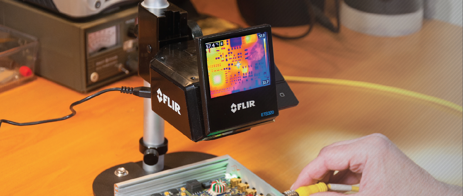
A Thermal Imager Made for the Benchtop
The breakthrough for Highland came with the FLIR ETS320 thermal imaging system. Designed for hands-free use in a lab with a microscope-style stand that’s quick to set up, it provided the stable platform Highland needed to place a PCB under the camera and electrically probe it without any shaking or vibration from the operator. Plus, the camera can easily be moved from one bench to another.
The camera maintains a constant, rigid focus point and distance, allowing the company to thermally image components so small, they couldn’t have measured the temperature any other way. The imager’s affordable cost means Highland is no longer limited to purchasing just one.
As Stanislowski explains, “The ETS320 is great because it’s mounted and has a convenient adjustable focus, and you can just set it up exactly where you need it, leaving your hands free to electrically probe or move the device around exactly as you need to.”
Larkin discovered just how useful the benchtop ETS320 imager was recently when he designed a board, built a prototype, tested it until he got it to work very well, and then thermal imaged it. He quickly discovered the transistors were running at almost 200 degrees Celsius. Even though the design worked beautifully, it would not have been reliable at that high temperature. The discovery enabled him to iterate the design and incorporate better transistors.
Likewise, Stanislowski’s team had a board with an FPGA that was getting too hot and kept shutting down. Using the ETS320 imager, his team quickly and easily measured the temperature of the FPGA under different circumstances and determined its operating limits. Then, to better handle the heat from the FPGA, the team added a heatsink and more airflow, and tightened up the specification limits on the operating temperature range.
At Highland, thermal imaging is now an integral part of both its engineering and evaluation of reliability and thermal stresses on new designs. It’s also used in testing. The ETS320 thermal imager, with its ease of use and hands-free measurement functionality, now makes the company’s benchtop thermal measurements faster, easier, and much more affordable. It’s a solid investment that has and will continue to return a huge reward for the company.
The FLIR ETS320 Thermal Imaging Solution
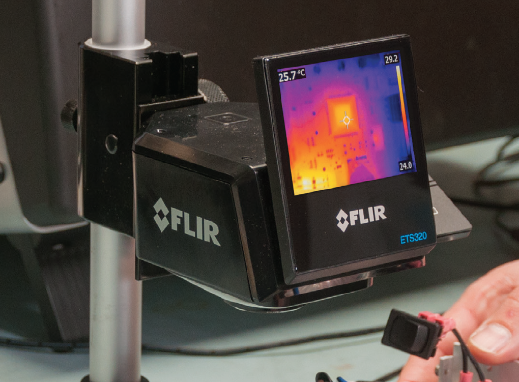
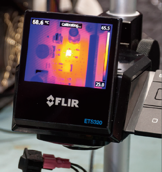
The FLIR ETS320 is a highly accurate, non-contact thermal measurement system for electronic board and device evaluation. It helps engineers and test technicians collect reliable data in seconds and analyze it quickly. Comprising a high-sensitivity infrared camera and integrated stand for hands-free measurement of PCBs and other small electronics, the ETS320 is specifically designed for laboratory work. A pole-mount allows for fast, easy setup and enables the camera to be easily moved from one bench to another. Simplified features allow users to focus on their work rather than on camera controls.
With 76,800 points of non-contact temperature measurement and a true 45° field of view, the ETS320 also improves product design. Additionally, its ability to detect design flaws that materialize as heat helps shorten product development time.
Key Features:
- 320 x 240 (76,800 pixel) IR resolution
- Vibrant 3-inch LCD display
- 45° field of view for broad initial scan to identify potential problems
- ±3 percent measurement accuracy promotes quality assurance and factory acceptance of PCBs
- Records standard radiometric JPEGs
- FLIR Tools+ software provided for instant analysis, including time versus temperature measurement


