10 + 1 Reasons why you aren’t measuring power accurately
- 11 Dec 2020

As energy efficiency becomes an important consideration for governments, industries and markets, engineers are looking to extract product efficiency by optimising power consumption and reducing losses. This has made accurate measurement of power an important element of quality control all the way from the design phase through to production and field operation. This article looks at key factors that affect power measurement accuracy and how to be mindful when choosing a measurement instrument.
1 . It’s not just about voltage and current uncertainties
For accurate analysis of power consumption, measurements must go beyond just voltage or current uncertainty and take power uncertainty as a whole into consideration. Factors such as crest factor, phase angle error, temperature range, warm-up time, stability period and common-mode rejection all influence the overall accuracy of a power measurement and as such should be specified and accounted for.
2. Validity of accuracy
Manufacturers of power measurement instruments often use ‘typical value’ specifications on their data sheets based on best case expectations from their product. These are not 100% guaranteed, certainly not without calibration anyway. Moreover, the accuracy of a power measurement varies depending on the measurement range. So any specified accuracy value should be accompanied by the range over which it is valid. Without this, a user cannot determine whether the accuracy values are valid only at a single point, a few points of a measurement range or the entire range. Be wary of instruments that offer impressive looking ‘typical’ values, they may not be as accurate as they claim.
3. Crest factor capability of the instrument
The crest factor of a waveform is its peak value divided by its RMS value; therefore a perfect sine wave has a crest factor of √2 or 1.414. Distorted waveforms particularly in switch mode power supplies can have very large crest factors. A power measuring instrument therefore needs to be able to handle waveforms with high crest factors accurately. Power measuring instruments with peak ranges typically specify maximum crest factors of 20; however instruments with RMS ranges are specified differently. For example, when a crest factor of 3 is selected on an RMS ranging instrument, it means that the instrument can handle this crest factor when the RMS input is at full scale. Therefore if the accuracy of the input is specified down to 1% of the measuring range, the instrument is capable of handling crest factors of 300, or even 600 when a crest factor of 6 is selected. Engineers should be aware of this when comparing instruments because this indicates how accurately an instrument can measure a signal and its distortions within a specified range.
4. Measurement range - peak or RMS?
As discussed earlier, the specified accuracy of an instrument is only valid over a specified range. But what if this range is specified differently in different instruments? Accuracy of an instrument when its range is specified in peak values, appear to look far more impressive than when using RMS. However, an accuracy value of 0.1% for example from a peak measurement range can correspond to 0.3% of an RMS measurement range for a crest factor of three. So the effect on the overall measurement error of a range error of 0.1% on a peak range is much worse than a 0.1% error on an RMS range. When calculating active power, the multiplication of voltage, current, the power factor and higher crest factors will magnify this effect dramatically.

5. Effects of harmonics
Harmonic measurement is another area where it is important to specify the accuracy in the context of the application. When left unaccounted for, harmonics can cause capacitance losses, undesired vibrations in motors, transformer losses in no load conditions, heating losses in conductors at higher frequencies, premature melting of fuses when electronic breakers don’t respond at designed levels and many more. It is therefore important to equip an engineer with the ability to detect harmonics and assess their effects on components, systems and subsystems within an application. Highly accurate instruments can measure harmonics upwards of the 500th order.
6. Zero crossing detection
For accurate power measurement, it is necessary for the power analyser to accurately detect the zero crossing of the current or voltage waveform. An average power measurement result is only stable when measured over a number of complete periods of the input signal. Without accurate zero crossing detection, the results will be inconsistent and not repeatable.
7. Phase error
Every power meter has a phase error associated with it due to the impedance of the input. Such impedance means that voltage and current inputs fed to the A/D converters drift further out of phase, resulting in a phase error represented by the active power formula for pure sine waveforms as:
P = Vrms * Irms * cos (φ ± δ) where δ is the phase error.
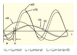
While this has no effect on RMS voltage or current or apparent power measurements, it does influence the measurement of active power and hence also the power factor. This phase shift should be specified by power analyser manufacturers to account for all boundary conditions that can affect phase angle error and other measurement errors.
8. Current sensors
Current sensors are often used in addition with or as an extension to a power measurement instrument. This means that the error/ uncertainty in the sensor will get added to the uncertainty of the input of the voltage as well as current shunt. It is therefore important to choose a sensor whose amplitude and phase uncertainty matches those of the high precision power analyser. There are different types of current sensors in the market. For high accuracy power measurement, the zero flux sensor is most often used. Unlike Hall Effect sensors that saturate over time or Rogowski coil sensors that offer lower accuracy zero flux sensors offer greater precision. They are also able to measure both DC and AC signals, which is important as invariably AC applications also have a DC component.
9 Common-mode rejection ratio (CMRR)
CMRR is a measure of how well an instrument rejects the unwanted interference voltages from an input signal common to both leads to the voltage input. When two input terminals are connected to each other with the reference as device ground, ideally there should be no influence on the measurement result. However leakage causes noise to be superimposed on the measurement signal and this in turn leads to measurement errors. It is therefore important to take this error and its uncertainty into account. For example, in inverter applications that encounter high voltage potentials with high-frequency components to ground, CMMR and its associated error becomes a significant factor.

10. Temperature effects
Electronic circuits behave differently at different temperatures, so a temperature coefficient should be specified to account for the associated temperature effects. The wider an instrument’s temperature range, the better. An instrument with specifications of 23°C ± 5°C for example can withstand temperature fluctuations (in heat producing measurement environments for example) better than an instrument with a 23°C ± 2°C specification. Unlike instruments that become unspecified outside a small temperature range, instruments with wider ranges don’t need expensive cooling solutions.
+1. Calibration and adjustment
However, no measurement is ever “correct”. There is always an unknown, finite, non-zero difference between a measured value and the corresponding ‘true’ value. In other words, a user can never be 100% sure that an instrument is operating within its specified tolerance limits. Regular accredited calibration is a method for gaining quantifiable confidence in a measurement system by comparing the instrument’s performance to a standard of known accuracy. It is also advisable to calibrate not just the measuring instrument but the extended measurement setup including sensors, cables, shunts and other devices that are part of a test bench.
But it’s not enough to calibrate at 50 - 60 Hz. Applications such as switch-mode power supplies, electronic lighting ballasts, soft starters in motor control systems and frequency converters in traction application etc. consume power at higher frequencies. Most calibration facilities do not calibrate at frequencies much above 60 Hz and well short of 100 kHz, and without an ISO 17025 accredited power calibration there is no guarantee that the measurements on an ISO 9001 certificate are correct. Depending on age and quality, a measurement instrument may drift out of specification due to temperature, humidity, oxidation, loading etc and may need to be ‘adjusted’ to bring it back within specifications. Instruments that need frequent or extensive adjustments are unreliable compared to instruments that only need this when a serious damage is being repaired.
Useful Links
Have a requirement? Speak to a technical sales engineer >


