Advanced Radar Analysis
- 11 Dec 2020
Advanced Radar Analysis
Tools for Measuring Modern Radars
Introduction
Time and Frequency Domain Analysis
Example Measurements
Examining Intended Signals
Unintended Signals
External Threats
Introduction
In designing modern electronic warfare and radar systems, you face significant challenges. You must develop solutions with the flexibility and adaptability required for next-generation threat detection and avoidance. To succeed, you need capable tools for the generation and analysis of extremely complex pulse patterns and you need to validate designs with advanced scanning methodologies – tools that can handle complex radar baseband, IF and RF signals as well as identify multi-system interference.
With today’s rapid advances in radar technology, developing and manufacturing highly specialized and innovative electronic products to detect radar signals takes leading-edge technology and tools. Tektronix innovative test equipment reduces testing uncertainty during the design process and delivers confidence in the integrity of increasingly complex designs. Tektronix Arbitrary Waveform Generators, Real-time Spectrum Analyzers and High-Bandwidth Oscilloscopes offer the capabilities you need to manage the requirements of modern radar applications. Real-time visibility of advanced pulse compression systems and the generation and analysis of all digital dynamic signal types help you create highly reliable, cost-effective system designs for defense and commercial electronic systems. The broad portfolio of Tektronix generation and analysis tools represents a scalable architecture that can protect your investments and speed your design development.
Time and Frequency Domain Analysis
Instrument Considerations
To understand the best measurement device, we need to understand the signals we are dealing with. First, we assume a sensor (Radar) or an ECM is mostly characterized as a time domain phenomenon, as fundamentally we are dealing with the transmission of a quantity of electromagnetic energy that illuminates a target - we then measure the time it takes for the reflected residual energy to arrive back at the receiver.
The signal could be a continuous wave or a sequence of pulses with a specific mission goal. However, pulse rise and fall times, the type of modulation and the behaviour of the transmitter amplifier and most importantly the frequency of transmission can create a broad range of responses that need to be considered.
Time domain measurements are traditionally performed with oscilloscopes while spectrum analyzers are best suited for frequency domain measurements. However, our problem is unique; in that we have time domain behaviours we want to observe, but they are exhibited in the frequency domain. While swept spectrum analyzers offer wide frequency and dynamic ranges, their ability to characterize time domain data is limited.
Oscilloscopes offer excellent time domain analysis, but lack in dynamic range especially at high frequencies. Advancements however in analog to digital converter technologies and in measurement instrumentation architectures such as FFT based analyzers or Vector Signal Analyzers capturing both the phase and amplitude components of the signal, or its vector) now allow for wide instantaneous bandwidth captures of high dynamic range time domain data in the frequency domain.
This is key when dealing with a transient/pulse-based time domain system with transmission frequencies in the giga-hertz ranges such as a radar or ECM.
Real Time Spectrum Analysis drives to the next level of insight. The advantage of real-time measurement capability is the ability to capture transient events in the frequency domain; real time multi-domain triggering, time-selective spectrum analysis, continuous wide bandwidth waveform storage and high-quality persistent displays that provide the higher levels of measurement capability and insight.
Signal Characteristics
As discussed, two types of signals need to be characterized, CW and Puled, with each having its own mission advantages and disadvantages.
CW Radar - Continuous-wave radar is a type of radar system where a known frequency of continuous wave radio energy is transmitted and then received from any reflecting objects.
Continuous-wave (CW) radar is excellent for calculating velocity using the Doppler effect by comparing the frequency shift of the received signal with that of the transmitted.
Test equipment needs to have the required broadband performance to capture the CW signal with enough frequency resolution to analyze the Doppler frequency shift.
Pulsed Radar - A pulsed radar emits short and powerful pulses and in the silent period receives the echo signals.
It is excellent for determining range by measuring the time difference between the transmitted pulses and the received pulses. The Doppler effect can also be observed to measure velocity, however it is usually calculated over multiple pulses.
Both types of radar could employ various types of modulation.
Measurement Considerations
For CW radar the instrument must be able to capture the transmission frequency plus the reflected doppler shifted frequency. For pulsed radar there are two options – the first is capture the lower frequency envelope information such as PRI (Pulse Repetition Interval) using a detector, or capture all the signals information with a broadband instrument such as a wide bandwidth Oscilloscope or Spectrum Analyzer. The darker line in Figure 1 shows the time domain envelope of the pulse and the lighter lines show the sinusoidal energy that fundamentally makes up the pulse.
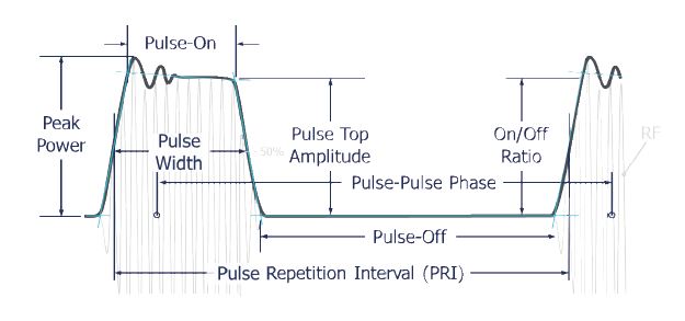
Figure 1. The autonomy of a pulse.
Another important factor is to ensure the instrument has enough bandwidth to capture the rise/fall times correctly. For example, an impulse radar may have a very short duration pulse therefore a very broadband oscilloscope may be the best tool to capture the pulse and characterize its parameters such as overshoot and rise and fall times. Very fast transition times or very short duration (sub-nanosecond or shorter) can be accurately seen on a 70 GHz bandwidth oscilloscope such as the DPO70000SX family.
Image 2
Figure 2. The DPO70000SX ATI Performance Oscilloscope delivers the industry’s most accurate capture of high-speed signal behaviour to verify, validate and characterize your next generation designs.
For measuring on/off ratio a wide amplitude is required. Understanding the dynamic range of the instrument is key for this measurement, sometimes referred to the dynamic range of an instrument, ab and can be expressed in decibels, actual bits or effective number of bits (ENOB).
For example, the Tektronix MSO 5 or 6 Series oscilloscope has a 12 Bit analog to digital converter (ADC) and can capture signals with up to 8GHz in bandwidth. In comparison to the lower performing MDO4000C oscilloscope that can capture up to 1GHz of bandwidth with 8 bits of resolution.
The MDO4000C has an optional Spectrum Analyzer built in, with an RF frequency range up to 6GHz. Not only does this allow for cross domain triggering, but it also provides higher dynamic range for frequency domain measurements. The MSO 5 or 6 Series can be used alongside a USB spectrum analyzer such as the RSA300 or RSA500 families when frequency coverage up to 18GHz and better dynamic range is required, especially for frequency domain measurements.
Image 3
Figure 3. The 5 and 6 Series MSO and RSA500 can be used together to perform multiple domain measurements.
If the pulse has vector modulation as used in data link or communication systems, this may require specialized demodulation measurements such as error vector magnitude(EVM). Advanced frequency and vector analysis is provided the SignalVu PC that can connect to both Oscilloscopes and Spectrum Analyzers.
Oscilloscope Measurements
The oscilloscope is the fundamental tool for examining varying voltage versus time. It is very well-suited for displaying the shape of baseband pulses. The origin of oscilloscope performance parameters traces back to characterizations of early radar pulses. Today’s real-time oscilloscopes have bandwidth up to 70 GHz, and are designed to capture and display either repetitive or one-shot signals.
Modern Oscilloscope triggering systems are very highly developed and can trigger on both analog and multiple channels of digital data. For example the MSO 5/6 series oscilloscopes eight input channels can be assigned as trigger inputs for both analog signals such as the envelope of an individual pulse, a defined stream of pulse envelopes or each channel can be assigned to a further eight digital inputs, providing the capability to trigger on multiple parallel data lines or words. Utilizing the external trigger RF devices such as the RSA300 or RSA500 families of spectrum analyzers can be triggered to perform frequency domain measurements based on real-time analog or digital domain events.
Figure 4. FastAcq shows a single too-narrow pulse out of many tens of thousands.
Pulse Measurements
The FastAcq feature of the oscilloscope operates on live time-domain data using DPX™ acquisition technology. All frequency domain measurements are made on the time sampled acquisitions of stored data.
The FastAcq display on the oscilloscope can discover baseband pulse time-domain transient errors. Figure 4 shows just one single pulse that has a narrower pulse width than even hundreds of thousands of correct pulses. The blue color on the temperature scale representation of signal persistency represents the least frequent occurrence, while the red areas are the parts of the signal that are the same every time.
The FastAcq capability on the DPO, DSA, and MSO Series provides a time-domain display with a high waveform capture rate. The DPX acquisition technology processor operates directly on the digital samples live from the A/D converter. It discovers rapid variations or one-shot events in the timedomain display.
For wideband measurements using an oscilloscope, FastAcq can be used to see even momentary transient events using the voltage vs. time display.
Figure 5 shows a one-time transient in blue. For this display, blue represents very low-occurrence transients, while red represents parts of the waveform that are constantly recurring.
Figure 5. Discovery of a single transient glitch in a train of pulses.
Oscilloscope Triggering
One of the most highly developed capabilities of the oscilloscope is triggering. Recent advances in oscilloscope trigger have enabled methods of triggering an acquisition or measurement based on the voltages and voltage changes in one or more channels.
These range in complexity from simple edge or voltage-level triggering to complex logic and timing comparisons for combinations of all of the input channels available. Pattern recognition, both parallel and serial, triggering on “runt” or “glitch” signals and even triggering based on commercial digital communications standards are all available in oscilloscopes.
The MSO 5/6 Series, DPO7000 and DPO/MSO/DSA70000 Series oscilloscopes allow the user to specify two discrete trigger events as a condition for acquisition. This is known as a trigger sequence, or Pinpoint™ triggering. The main or “A” trigger responds to a set of qualifications that may range from a simple edge transition to a complex logic combination on multiple inputs. Then an edge-driven “B Delayed” trigger can be specified to occur after a delay expressed in time for events.
The B-trigger is not limited to edge triggering. Instead, the oscilloscope allows the B-trigger to look, after its delay period, for a condition chosen from the same broad list of trigger types used in the A-trigger. A designer can now use the B-trigger to look for a suspected transient, for example, occurring hundreds of nanoseconds after an A-trigger has defined the beginning of an operational cycle. Because the B-trigger offers the full range of triggering choices, the engineer can specify, for instance, the pulse width of the transient they want to find. Over 1,400 possible trigger combinations can be qualified with Pinpoint triggering.
Sequences can also include a separate horizontal delay after the A-trigger event to position the acquisition window in time.
The Reset Trigger function makes B-triggering even more efficient. If the B-event fails to occur, the oscilloscope, rather than waiting endlessly, resets the trigger after a specified time or number of cycles. In so doing it rearms the A-trigger to look for a new A-event, sparing the user the need to monitor and manually reset the instrument.
The system can detect transient glitches less than 200 ps wide. Advanced trigger types, such as pulse width trigger, can be used to capture and examine specific RF pulses in a series of pulses that vary in time or in amplitude. Trigger jitter – a crucial factor in achieving repeatable measurements – is less than 1 trillionth of a second (1 ps) rms.
For baseband pulses, the triggers based on edges, levels, pulse width, and transition times are of the most interest. If triggering based on events related to different frequencies is needed, then the RSA Series spectrum analyzer is required.
Manual Timing Methods
Traditional measurements of pulses were once made by visual examination of the display on an oscilloscope. This is accomplished by viewing the shape of a baseband pulse. The measurements available using this method were timing and voltage amplitude. These measurements were sufficient, as pulses were generally very simple.
The baseband pulses were used to modulate the power output of the radar transmitter. If it was necessary to measure the RF-modulated pulses from the transmitter, then a simple diode detector was often used to rectify the RF signal and provide a reproduction of its baseband timing and amplitude for the oscilloscope to display. Generally, the oscilloscope did not have sufficient bandwidth to be able to directly display the RF-modulated pulses, and if it did, the pulses were difficult to clearly see, and was even more difficult to reliably generate a trigger.
For these baseband pulse measurements, the measurement technique first used was to visually note the position onscreen of the important portions of the pulse and count the number of on-screen divisions between one part of the pulse and another. This is a totally manual procedure performed by the oscilloscope operator and as such was subject to errors.
Automated Oscilloscope Timing Measurements
With the advent of Analog-to-Digital converters, the process of finding the position on-screen became one of directly measuring the time and voltage at various portions of the pulse.
Now there are fully automated baseband pulse timing measurements available in modern oscilloscopes. Single button selection of rise time, fall time, pulse width, and others are common. However, most of these measurements do not focus on the measurement envelopes of modulated radar signals.
When used on pulse-modulated carriers, these measurements are of limited utility, because they are presented with the carrier of the signal instead of the detected pulse. This results in pulse width measurements that are made on a single carrier cycle, and rise times of the carrier instead of the modulated pulse. Detectors may be used on the input of the oscilloscope to remove the carrier and overcome this.
Figure 6. Spectrum plot measurements of pulse width and repetition rate.
When choosing the correct tool, most engineers us an oscilloscopes when performing time domain measurements, but spectrum analyzers are best suited for frequency domain measurements. As discussed earlier, radar and EW is unique, in that time domain behavior is exhibited in both the time and frequency domain. A swept spectrum analyzer offers wide frequency and dynamic ranges, but its ability to characterize time domain data is limited. Oscilloscopes offer excellent time domain analysis and trigger capability, but lack in dynamic range, especially at high frequencies.
Advancements in analog to digital converter technologies and in measurement instrumentation architectures such as FFT based analyzers or Vector Signal Analyzers (the instrument capture both the phase and amplitude components of the signal, or its vector), now allow for wide instantaneous bandwidth captures of high dynamic range time domain data in the frequency domain. This is key when dealing with a transient/pulse-based time domain system with transmission frequencies in the giga-hertz ranges such as a radar or ECM.
Real Time Spectrum Analysis drives to the next level of insight. The advantage of real-time measurement capability is the ability to capture transient events in the frequency domain; real time multi-domain triggering.
Figure 7. Alternate instrumentation block diagrams.
Figure 7 puts it all into context. All architecture use a super heterodyne process to convert high frequency signals to a lower frequency for analysis. The swept spectrum analyser essential only measures the power in a filter (Resolution Bandwidth Filter) at a specific frequency point derived from the frequency of the Local Oscillator (LO). It can display a range of power vs frequency by ‘sweeping’ the LO and the x-axis of display. This allows for very broad frequency displays with excellent dynamic range, but the time domain acquisition bandwidth is limited to that of the resolution bandwidth filter.
A Vector Signal Analyzer uses a fixed local oscillator, with a much larger IF filter (instead of the RBW filter bank). This allows us to acquire large amounts of time domain data, then either display it as time domain data translate it to the frequency domain utilizing an Fast Fourier Transform. A Real Time Spectrum Analyzer conceptual is the same as a VSA, however more processing is performed earlier in the signal chain allowing for faster processing of FFT’s and triggers thus providing the enhanced measurement capability required for a successful test.
What this all means is that the RTSA architecture allows us to observing time varying behaviours in the Electromagnetic Spectrum, analysis in the time and frequency domain the systems under test behaviour, while simultaneously recording the events to a hard disk array.


